Step 2: Wire the hardware
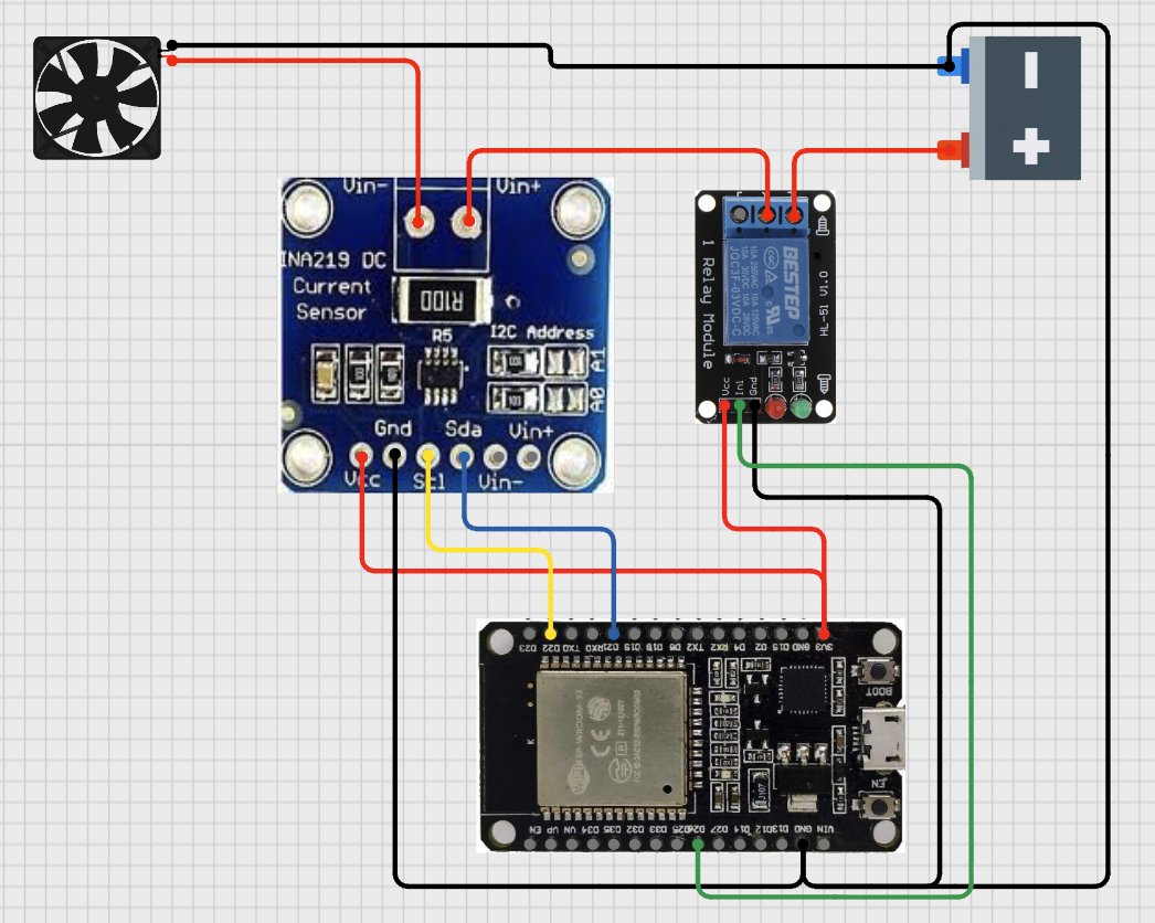
Make four connections:
| From | To | Purpose |
|---|---|---|
| ESP32 GPIO 21 | INA219 SDA | I2C data |
| ESP32 GPIO 22 | INA219 SCL | I2C clock |
| ESP32 GPIO 26 | Relay signal | Relay control |
| Load positive lead | INA219 Vin+ and Vin- in series | Current measurement path |
Power the INA219 from the ESP32's 3V3 pin. Power the relay module from 5V. Share a common ground across all three.
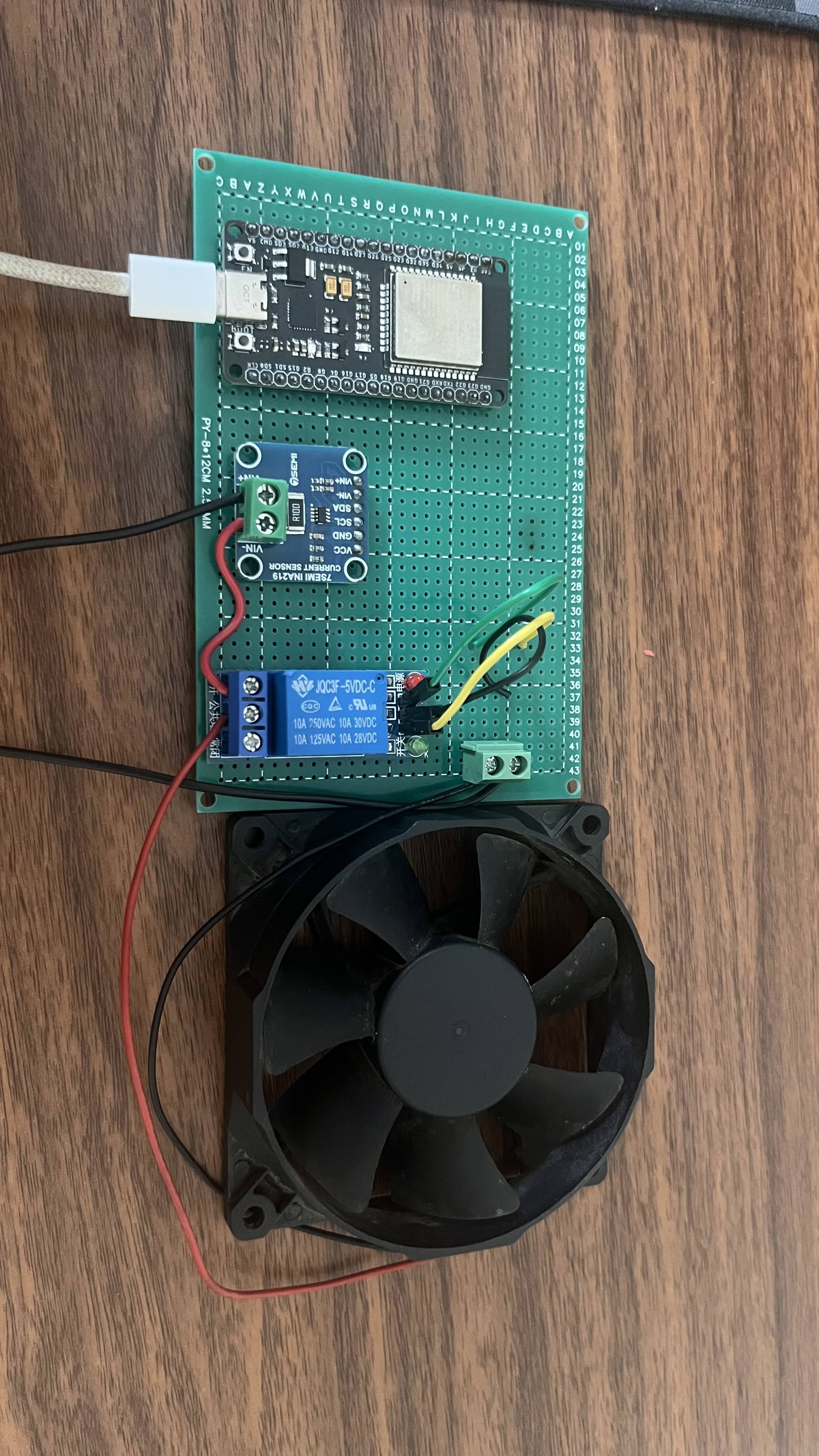
This build was prototyped on a veroboard. The load is powered from an old phone charger (100-240V, 60Hz, 0.3A input; 5V, 0.6A output). A cheap USB-output charger is a convenient low-voltage supply for a first prototype.
Mains voltage is dangerous. Do not attempt this build without someone more experienced present. The author assumes no responsibility for any damage to equipment, injury, or loss. Use a low-voltage load (USB-powered bulb, USB fan, 5V LED strip) for your first prototype. Never wire a mains-voltage load through the relay contacts unless you have the training and equipment to do it safely.
The relay module used in this tutorial is active-LOW. Pulling GPIO 26 LOW closes the contact. The firmware initializes the pin HIGH before WiFi starts, so the relay stays open during boot.